In a hydraulic system, a single small threaded fitting often determines the life or death of the entire equipment. With a multitude of thread types and varying standards—M, G, R, NPT, JIC—these codes represent a battlefield of industrial standards and a minefield that engineers must navigate. This article will systematically deconstruct the genetic code of hydraulic threads, from basic identification to precise selection, helping you to permanently end the nightmare of connection leaks.

I. Fundamentals and Classification of Hydraulic Threads
1.1 Basic Elements of a Thread
To accurately identify a thread, you must first understand its "DNA." A thread is not a simple spiral line; it is a continuous raised structure formed on a cylindrical or conical surface along a specific path, with every parameter holding a secret.
1.2 Classification of Hydraulic Threads
The world of hydraulic threads is primarily divided into two camps: Pipe Threads, born for fluids and dedicated to pipe connections with leak prevention as their primary mission; and Standard Threads, mainly for fastening with connection as a secondary function, commonly found in hydraulic valve block mounting holes, which do not have sealing capabilities on their own and must rely on O-rings or bonded washers.

II. A Detailed Look at Major Hydraulic Thread Standards
2.1 Metric Threads
Led by ISO, designated with "M," and featuring a 60° thread angle. For example, `M20×1.5`. In hydraulic systems, metric threads typically do not seal directly through the threads themselves. It is crucial to check for a chamfer or counterbore on the mating face, which indicates the need for a bonded washer or an O-ring.
2.2 British Pipe Threads (BSP)
Characterized by a 55° thread angle. They are divided into sealing pipe threads (R/Rc, or BSPT), which rely on a 1:16 taper for a metal-to-metal seal, and non-sealing pipe threads (G, or BSPP), where the threads only provide clamping force, and sealing is entirely dependent on an O-ring or ED seal on the end face.
2.3 American Pipe Threads (NPT)
Designated as "NPT," with a 60° thread angle, and are also tapered pipe threads. A critical pitfall is that the NPT thread angle differs from the British R thread (60° vs. 55°). Forcing them together will cause permanent leakage.
2.4 SAE Thread System
This system represents the modern trend in hydraulic connections—relying on elastomeric seals. Examples include JIC (37° flare for metal-to-metal contact seal) and ORB (straight thread with an O-ring seal).
III. Identification Methods and Tools for Hydraulic Threads
3.1 Visual Inspection
Observe the shape: tapered threads are likely NPT or R, while straight, parallel threads are M, G, or UN. Examine old fittings: residue of thread seal tape often indicates tapered pipe threads, while a flattened O-ring points to SAE or G threads.
3.2 Measurement with Tools
Follow these three hardcore steps: 1. Measure the major diameter with calipers (for tapered threads, measure at the 4th or 5th thread); 2. Measure the pitch with a thread gauge (it must fit snugly); 3. Measure the thread angle with an angle gauge (to distinguish NPT's 60° from BSPT's 55°).

3.3 Interpreting Markings
For example, NPT 1/2-14 denotes an American tapered pipe thread with a nominal size of about 1/2 inch. In M20×1.5-6H, 6H represents the tolerance class of the internal thread.
IV. Practical Application: Selection and Installation of Hydraulic Threads
4.1 Selection Principles
When selecting, you must ensure that the thread standard, diameter, pitch, and thread angle are all identical. Mixing fittings of different standards is the number one cause of leaks.
4.2 Installation Standards
Use a torque wrench to control the pre-tightening force, preventing overtightening that can cause cracking or undertightening that leads to leaks. Before installing tapered threads, hand-tighten them for 2-3 turns to align the angle. Only tapered threads require the use of thread seal tape or sealant.
4.3 Case Study
A mining excavator experienced a catastrophic failure after a BSPT 3/8 (55° angle) fitting was mistakenly used to replace the original NPT 3/8 (60° angle) fitting. Under high pressure, the connection burst, causing a fire. This tragic case warns us that a 5° difference in thread angle is fatal in high-pressure systems.
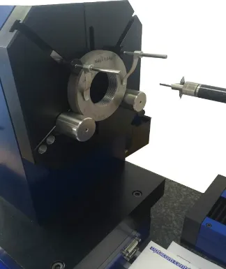
V. Future Trends: Intelligent Thread Identification Technology
With the advance of Industry 4.0, the era of relying on the "naked eye" of seasoned technicians to identify threads is passing. Vision inspection systems, AI-powered image recognition apps, and digital twin technology are eliminating selection errors at the source, making thread identification smarter and more precise.
Conclusion
The reliability of a hydraulic system is built upon the smallest details. Thread identification may seem tedious, but it is a hardcore fundamental skill that every engineer must master. Remember: the difference between 55 and 60 degrees is not a numbers game—it is the dividing line between safety and disaster.


